Tools Used
There are a variety of tools that are required to design and construct the Dimebots. The 3D Printed PLA body and drive wheel uses the Autodesk Fusion 360 design software. This enables rapid design development of the physical pieces needed for the Dimebots and the ability to export STL (stereolithography) files that can be used in the process of 3d Printing.
The Ultimaker Cura 3D Printer slicing software is used to create the required g-code files that are used by the 3D Printer for the actual printing process.
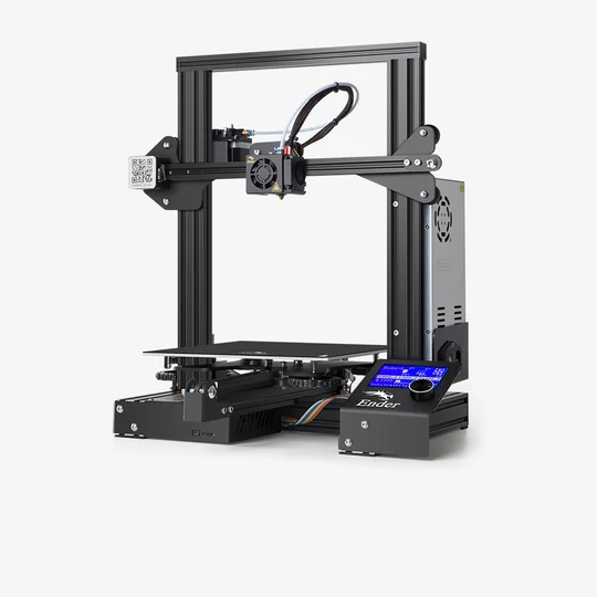
For the 3D Printing of the physical parts of the Dimebots, the Creality Ender 3 is used as the 3d Printer.
The 7.7.0 version of the Eagle CAD software is used as the tool for the development of schematics and PCB board layouts of the Dimebots.
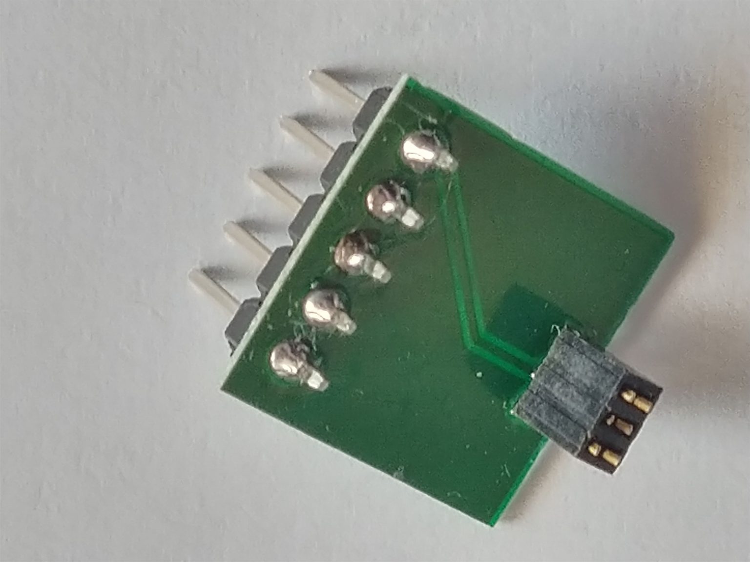
The Unified Program and Debug Interface (UPDI) is a Microchip proprietary interface for external programming and on-chip debugging of a device. It is a successor to the PDI two-wire physical interface, which is found on all AVR XMEGA devices. UPDI is a one-wire interface providing a bidirectional half-duplex asynchronous communication with the target device for purposes of programming and debugging. A fast signal Schottky diode such as one of the BAT series (BAT43, BAT54) is soldered between TX and RX to allow for reliable UPDI programming at 230400 baud. A custom PCB board that adapts the CH340G USB to Serial TTL Converter to the Dimebots using a 3 position 1.27mm connector is used for programming the Dimebots.

